Foam is everywhere in manufacturing: protecting parts in transit, organizing tools on factory floors, cushioning sensitive equipment, and supporting production workflows.
But the way custom foam is produced hasn’t changed much in decades. Most manufacturers still rely on supplier-driven workflows involving quoting, tooling, cutting, bonding, assembly, and long lead times, often for parts that require customization, iteration, or low-volume production.
For engineers specifying a custom insert, operations teams standardizing shadow boards across facilities, or manufacturers producing low-volume custom solutions, those constraints create unnecessary cost and operational friction.
3D printed foam changes the economics of foam fabrication by replacing fragmented workflows with a fully digital manufacturing process. This guide explores how 3D printed foam works, how it compares to traditional fabrication methods, and where it delivers the most value across packaging, organization, and production applications.
What Is 3D Printed Foam? How the Process Works
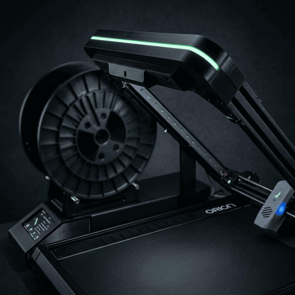
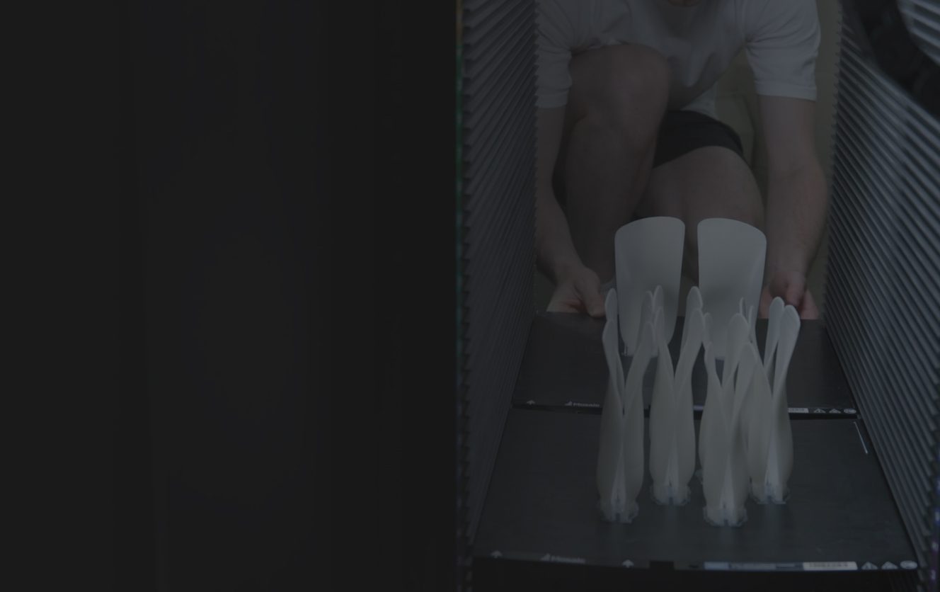
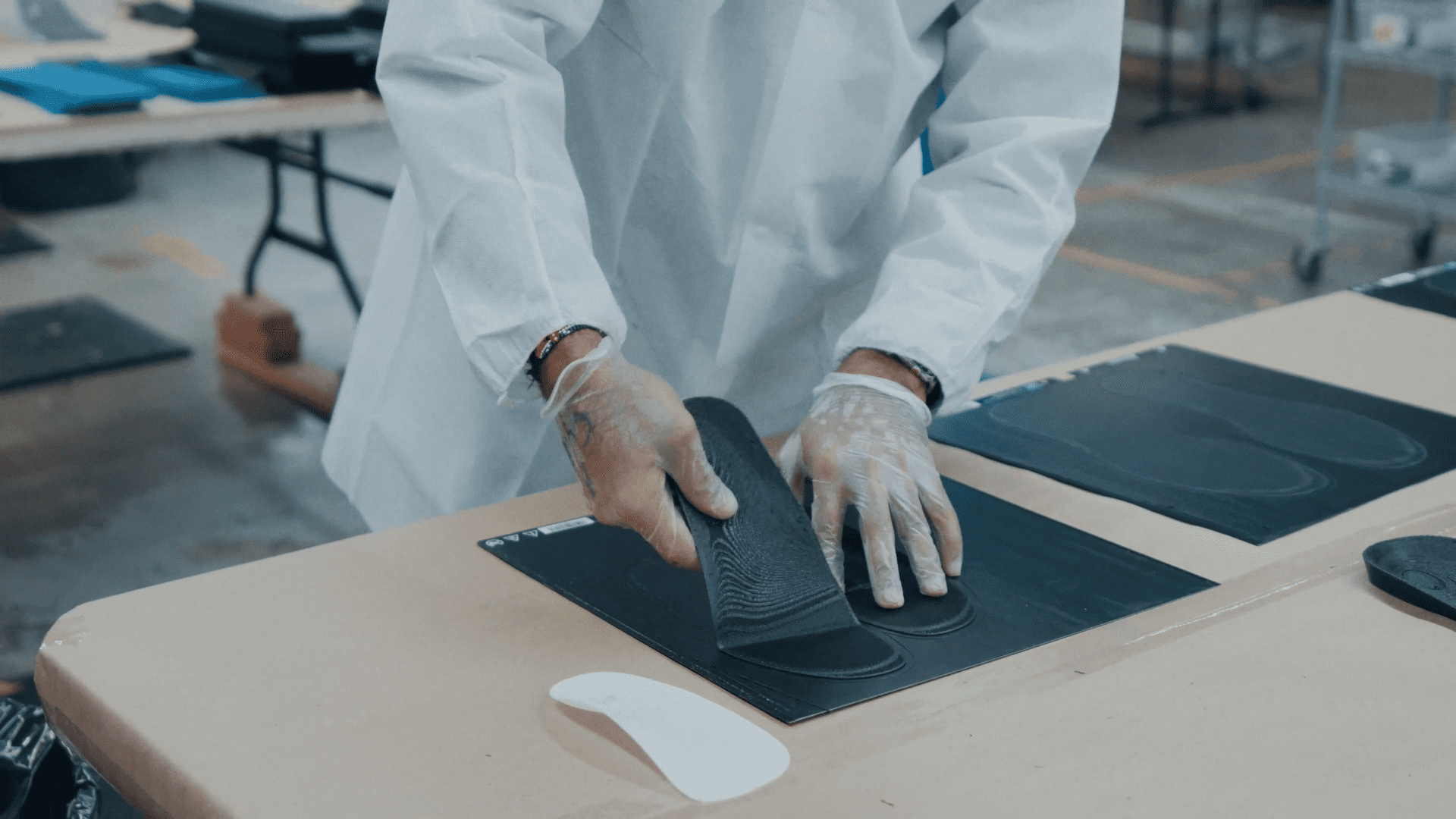
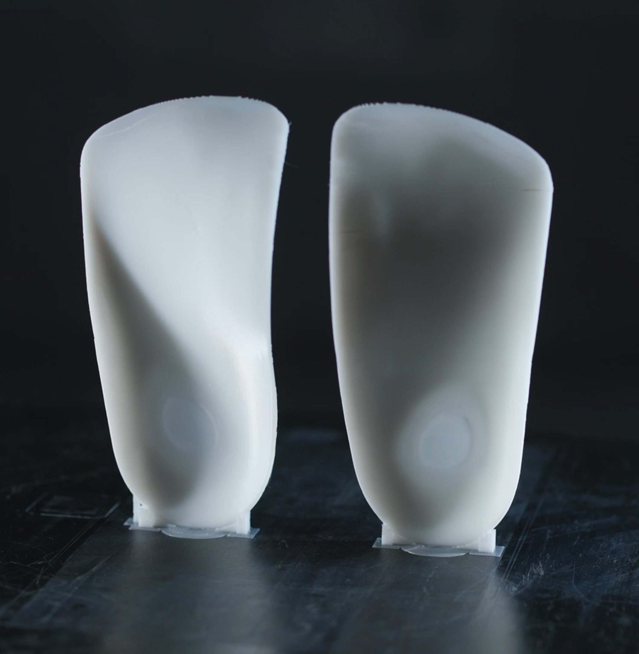
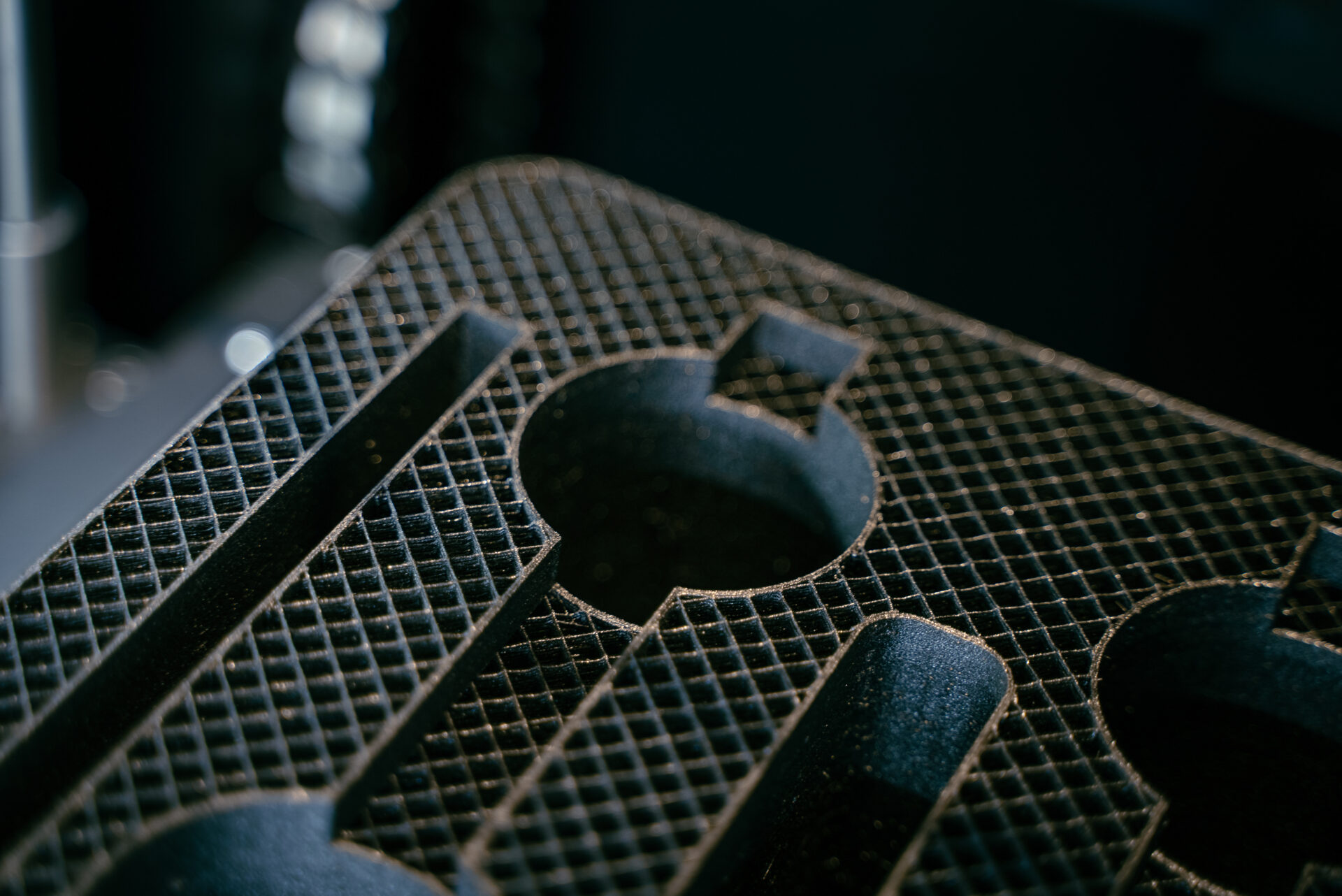
3D printed foam uses Fused Filament Fabrication (FFF) – the same deposition process used for rigid plastics, with foamed elastomeric filament instead of standard thermoplastics. The printer extrudes a structurally defined material, producing parts with flexible, compressible, and energy-absorbing characteristics similar to traditional engineered foam materials.
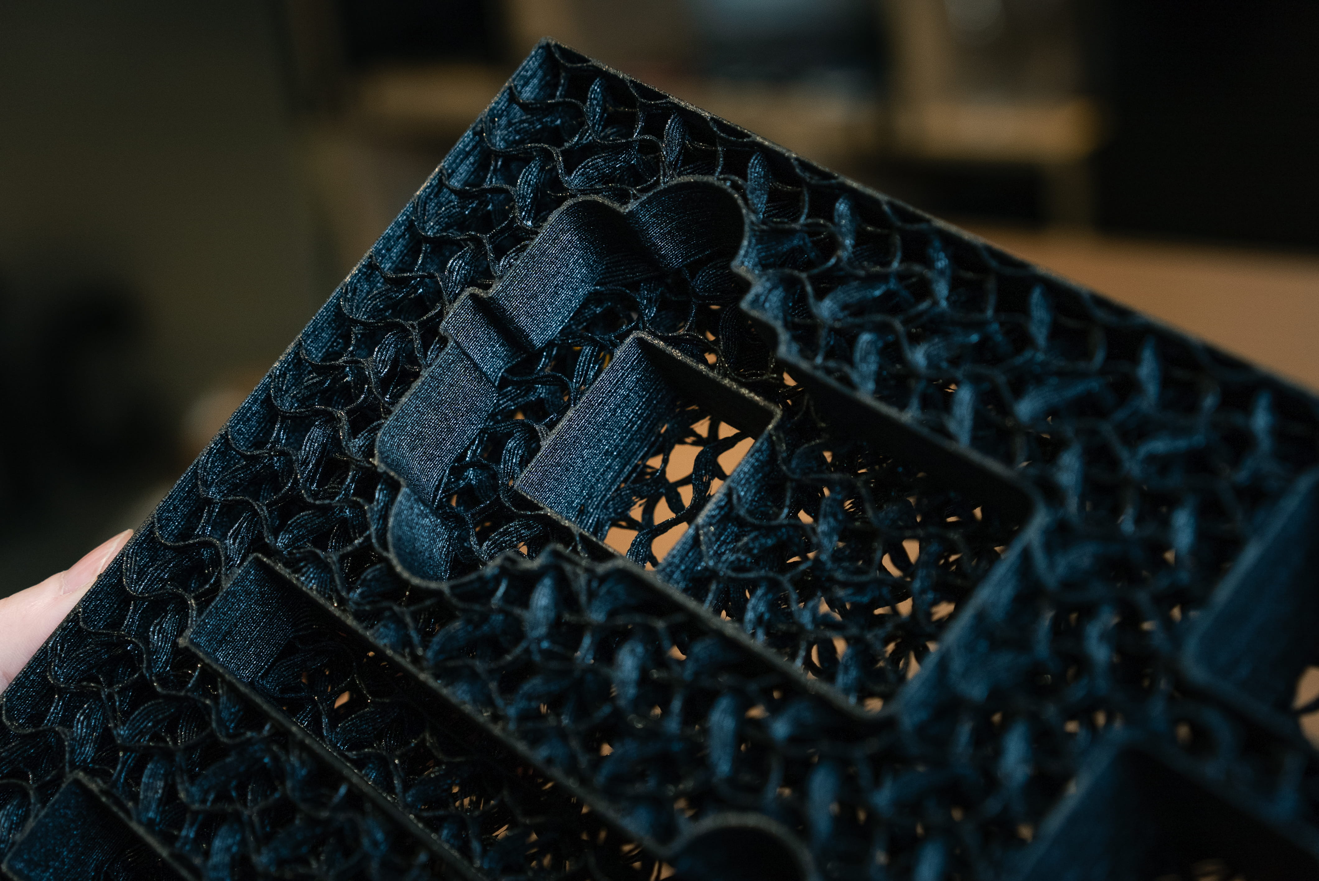
The key distinction from standard FFF is that the material itself foams during extrusion. This creates a cellular microstructure within the part, not just soft geometry, but genuine cushioning behavior across a controlled range of compression and recovery.
Mosaic Stitch is Mosaic’s proprietary foamed elastomeric material, engineered as a replacement for traditional PE, XLPE, and EVA foam workflows. Combined with additive manufacturing, it enables manufacturers to produce finished foam parts directly from digital files, without tooling, cutting, bonding, or assembly.
Stitch processes on compatible FFF platforms without requiring dedicated foam fabrication equipment or process chemistry, enabling on-demand, localized production using a fully digital workflow.
3D Printed Foam vs. Traditional Foam: A Direct Comparison
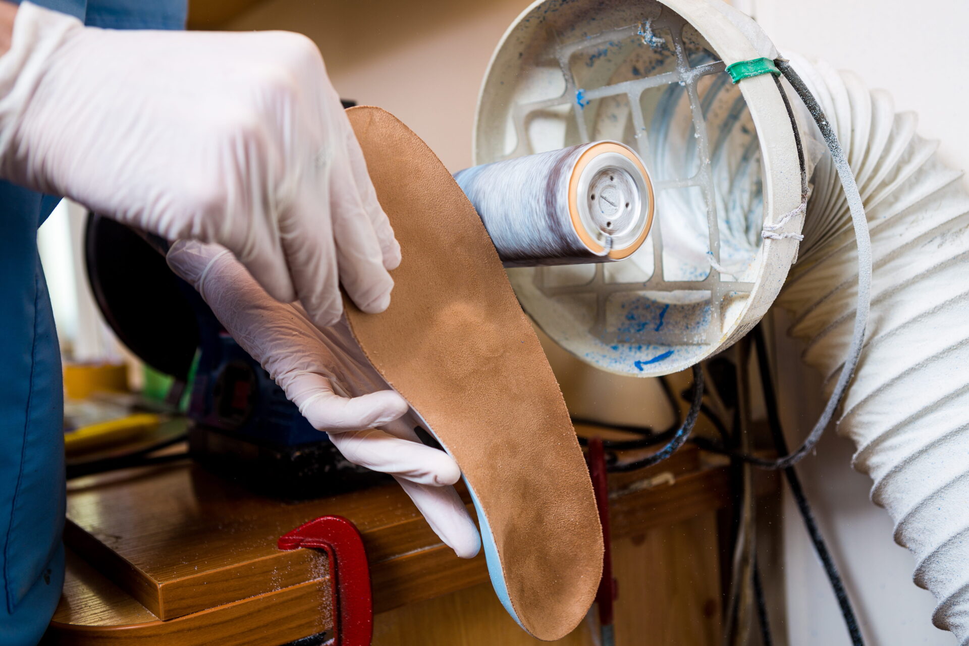
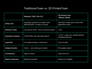
Traditional foam fabrication covers several processes: waterjet cutting, CNC routing, die-cutting, and hot-wire cutting, all typically followed by adhesive lamination and hand finishing to build up multi-layer or complex geometry. Each has its place at volume. None is well-suited to low quantity, high complexity, or fast iteration.
Key Applications: The Three Pillars of 3D Printed Foam
3D printed foam delivers value across three distinct application categories, each with its own buyer logic, design requirements, and ROI profile.
Pillar 1: Protective & Presentation
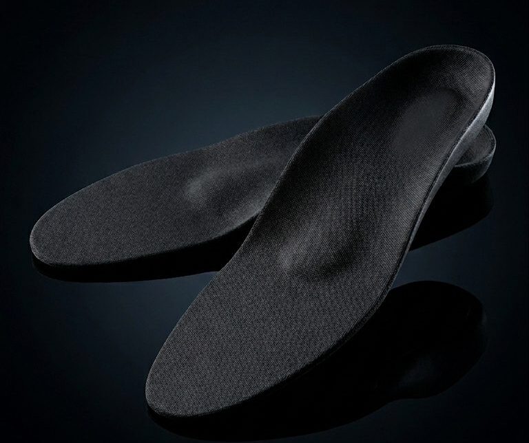
Custom packaging inserts, case liners, instrument trays, and device presentation packaging.
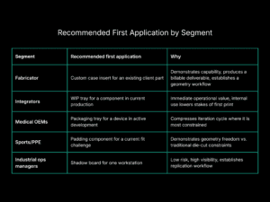
Who this is for: Fabricators fulfilling custom insert orders, integrators building presentation-ready deliverables, medical OEMs iterating on device packaging, and sports/PPE manufacturers working with complex geometry.
Where traditional methods fall short: A machined aluminum case insert for a precision instrument requires an exact foam profile. Traditional fabrication means submitting a drawing, waiting for a waterjet shop to schedule the cut, and laminating multiple layers to achieve the required depth. Any geometry revision, a component change, a regulatory update, a new SKU, restarts the process.
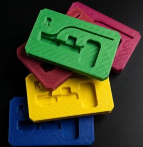
What 3D printing enables: A single print produces the full geometry, recesses, retaining lips and graduated compression zones – without assembly. Design changes take minutes. A medical device company iterating on tray geometry between design reviews can produce ten variants in the time it would previously take to receive one.
See how this played out for a real pharmaceutical packaging application
Pillar 2: Organization & Visibility
Shadow boards, tool outlines, 5S station setups, and visual management systems.
Who this is for: Industrial operations managers running lean programs, maintenance departments managing tool accountability, and facilities teams standardizing workstation layouts across multiple sites.
Where traditional methods fall short: A foam shadow board for a CNC workstation is a precision item. Every tool has a silhouette, a depth, a retention requirement. Traditional production requires hand tracing, waterjet cutting per panel, and manual finishing, with no reliable method for replication across facilities other than doing it again from scratch.
What 3D printing enables: The shadow board profile is a digital file. It prints exactly the same whether it’s the first copy or the fiftieth, at the same facility or at a plant in another country. For organizations standardizing operations across facilities, this transforms shadow boards from one-off projects into scalable, repeatable production assets
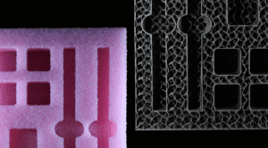
Variable density is particularly valuable here: the visible surface of a shadow board can be printed firm enough to hold shape and resist wear, while retention zones are printed softer for tool insertion and extraction without damage.
Pillar 3: Production & Handling
Dunnage, WIP trays, kitting foam, line-side fixture support, and part protection during intra-facility transport.
Who this is for: Industrial operations managers reducing motion waste and part damage, integrators building custom handling solutions into larger system deliverables, and manufacturing engineers specifying WIP flow at the component level.
Where traditional methods fall short: Production foam is often an afterthought, generic sheet foam cut to approximate dimensions, stacked in a bin, and relied upon to prevent contact damage between parts it was never designed to protect. When a part changes, the foam is discarded and replaced with more generic material. When a process moves, the foam doesn’t move with it.
What 3D printing enables: Dunnage and WIP trays designed to the part, not approximated. A printed WIP tray holds a machined component in a specific orientation, prevents contact between surfaces that cannot touch, and can be reprinted immediately when the part geometry changes. Kitting foam ensures that every component in a kitted assembly ships in the correct location, reducing errors at the point of use.
From a lean perspective, purpose-built production foam eliminates the motion waste of workers searching for correct orientation, reduces part damage during handling, and supports standardized work by making the correct handling method physically obvious.
Protective & Presentation
The requirements for protective and presentation foam are among the most demanding in the category. A custom insert for a surgical instrument tray must hold each instrument without contact between cutting edges. A presentation case for a high-value electronics assembly must protect during transit, present cleanly at delivery, and communicate quality to the end customer. A sports padding component must conform to body geometry, provide graduated impact response, and survive repeated compression cycles.
Traditional foam fabrication handles these requirements through assembly: layers of different density foam, cut and laminated to build up the required profile. The more complex the geometry, the more assembly steps, and the more opportunities for dimensional error.
Printed foam handles complexity natively. A single part can incorporate:
- Variable density zones: firm retention walls, soft contact surfaces, printed in the same operation without adhesives or assembly
- Undercut geometry: recesses that grip a part without requiring a split tool or lamination
- Integrated features: alignment posts, stacking geometry, identification markings, as part of the print, not additions
- Surface finish control: texture and finish adjustable through print parameters, not secondary operations
For medical device OEMs, the iteration speed is particularly significant. Packaging validation is part of device approval, and packaging designs frequently change as device designs evolve. The ability to update a file and print a revised tray the same day, rather than waiting weeks for tooling, compresses development schedules in a meaningful way.
Organization & Visibility
Shadow boards are the most visible output of a lean 5S implementation, and often the least systematically produced. Most facilities approach shadow board fabrication as a facilities project: a technician traces tool outlines, a shop cuts the foam, and the result is installed. When tools change or workstations are reconfigured, the process starts over.
At scale, multiple departments, multiple facilities, multi-site manufacturing networks, this approach doesn’t hold. Inconsistency between shadow boards creates inconsistency in work standards. A tool silhouette that’s slightly off means tools don’t fit or don’t hold. A board that wears out and can’t be exactly replicated undermines the visual management system it was meant to support.
3D printed shadow boards address the replication problem directly. Once a board is designed and validated at one workstation, the file is the standard. Every subsequent board, whether a replacement at the same station or a rollout to a new facility, is printed from the same file to the same specification.
Design considerations for printed organization foam:
- Tool silhouettes are modelled from actual part geometry, ensuring exact fit and retention
- Color can be used to designate tool categories, departments, or workstation types, printed in material color rather than painted or taped
- Panel geometry can be adapted to specific board or cabinet dimensions without retooling
- Retention depth and firmness can be tuned per tool type, heavier tools held more firmly, frequently-used tools with easier release
For maintenance and MRO operations where tool accountability directly affects safety and compliance, a shadow board system that can be precisely replicated and efficiently maintained is not a lean nicety, it is a process control requirement.
Production & Handling
The cost of inadequate production foam is often invisible until it isn’t. Part contact damage that accumulates during WIP handling, orientation errors during kitting, and surface scratches that only appear at final inspection are all symptoms of foam that was designed for approximation rather than precision.
Printed dunnage and WIP trays change the specification standard for production foam. Instead of “soft foam, approximately this size,” the specification is a geometry: a defined cavity for each part, designed to the part’s actual dimensions and handling requirements.
Part-specific WIP trays
It hold components in a defined orientation throughout the production process. For machined or precision-ground parts, this eliminates the contact damage that occurs when parts shift in generic foam. For assemblies with multiple components, the tray enforces kitting accuracy by making incorrect placement physically impossible.
Line-side dunnage
It supports parts at workstations where manual assembly operations occur. A printed foam nest positions a component for an operator at the correct angle and height, reducing handling time and eliminating the postural adjustments that accumulate into ergonomic risk.
Transit dunnage
Kitting foam
For multi-site manufacturing operations, printed production foam offers the same replication advantage as shadow boards: a file, not a process, defines the standard. The same dunnage geometry ships from the design office to every facility that runs the same part.
Learn more about what we do https://mosaicmfg.com/foam/
Mosaic Stitch: Material Specs & Performance
Stitch is Mosaic’s foamed elastomeric filament, developed specifically as an FFF-printable replacement for PE, XLPE, and EVA foam substrates. Its material properties are engineered to match the functional requirements of those substrates in protective, organization, and production foam applications.
Mechanical properties
- Tunable density via print parameters, no material change required for different density zones
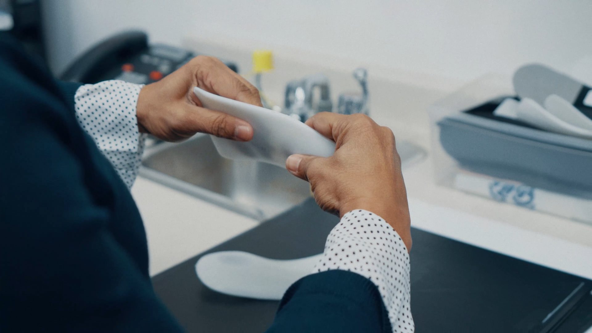
- Controlled elasticity with high recovery after compression
- Abrasion resistance suitable for repeated handling and tool insertion/extraction
- Chemical resistance to common industrial fluids, cleaning agents, and light solvents
Processing properties
- Compatible with standard FFF hardware, no dedicated machinery required
- Processes on existing slicer profiles with minimal adaptation
- No special enclosure or atmospheric control required
- Consistent extrusion behavior across supported hardware platforms
Surface and aesthetic properties
- Surface finish adjustable through print parameters (layer height, speed, infill pattern)
- Available in multiple colors, color used as a functional differentiator in organization applications
- No secondary finishing required for most applications
Performance as a PE/XLPE/EVA replacement
3D Printing for Foam: The End-to-End Workflow
One of the persistent objections to adopting any new fabrication process is workflow integration: what does it add to an existing operation, and what does it eliminate?
For foam specifically, the traditional workflow involves design, drawing preparation, vendor quoting, tooling (for die-cut) or programming (for waterjet/CNC), production scheduling, fabrication, and delivery. Between design and the first part, four to six weeks is common.
Between the first part and an approved revision, another two to four.
The printed foam workflow compresses this to three steps:
Design
Model the part in any standard CAD environment. For inserts, import or reference the part geometry being packaged and build the cavity from it. For shadow boards, scan or model the tools. For dunnage, model from part drawings or scans. Existing CAD tools and practices apply, no new software required.
Export to STL or equivalent, slice with an existing FFF profile adapted for Stitch, print. For most applications, print time is measured in hours. A standard case insert prints overnight; a shadow board panel in a few hours; a WIP tray in under an hour.
Use
Remove the part from the build plate, perform any required support removal, and deploy. No waterjet operator, no lamination press, no curing time, no finishing labor. The part comes off the printer ready to use.
For fabricators and integrators, this workflow means fulfilling custom foam orders in-house, on-demand, without vendor dependency. For industrial operations, it means maintaining foam standards without a procurement cycle. For medical OEMs, it means iterating on packaging during device development without scheduling delays.
How to Get Started: Printers, Slicer Setup & First Applications
Compatible hardware
Stitch is compatible with FFF printers that support flexible filament and allow appropriate nozzle sizing. Most open-frame and enclosed FFF platforms used in professional and industrial environments are suitable. Contact Mosaic for a current hardware compatibility list.
Slicer setup
Ready to Evaluate 3D Printed Foam?
Whether you’re producing custom packaging inserts, shadow boards, dunnage, or other foam components, the core question is the same: can your current manufacturing process deliver the speed, flexibility, and cost-efficiency required for today’s production demands?
Mosaic helps manufacturers evaluate and implement Stitch 3D printed foam solutions for applications where traditional fabrication methods struggle with lead times, geometry complexity, or low-volume economics. From initial assessment through deployment, our team works with you to identify opportunities for improved efficiency, reduced waste, and streamlined production.
Contact our team to discuss whether Stitch is the right fit for your foam manufacturing application.